After What Fraction of Period T Will the Current Again Have Its Initial Value
Inductance
97 Oscillations in an LC Excursion
Learning Objectives
By the terminate of this section, you will be able to:
- Explicate why charge or electric current oscillates between a capacitor and inductor, respectively, when wired in series
- Draw the relationship between the accuse and electric current aquiver betwixt a capacitor and inductor wired in series
Information technology is worth noting that both capacitors and inductors store energy, in their electric and magnetic fields, respectively. A circuit containing both an inductor (L) and a capacitor (C) can oscillate without a source of emf by shifting the energy stored in the excursion between the electric and magnetic fields. Thus, the concepts we develop in this section are straight applicable to the commutation of energy between the electric and magnetic fields in electromagnetic waves, or light. We commencement with an idealized circuit of zero resistance that contains an inductor and a capacitor, an LC excursion.
An LC circuit is shown in (Figure). If the capacitor contains a accuse  before the switch is airtight, and then all the energy of the circuit is initially stored in the electric field of the capacitor ((Figure)(a)). This energy is

When the switch is closed, the capacitor begins to discharge, producing a electric current in the circuit. The current, in plow, creates a magnetic field in the inductor. The internet consequence of this process is a transfer of energy from the capacitor, with its diminishing electrical field, to the inductor, with its increasing magnetic field.
(a–d) The oscillation of charge storage with changing directions of electric current in an LC circuit. (e) The graphs show the distribution of charge and current betwixt the capacitor and inductor.
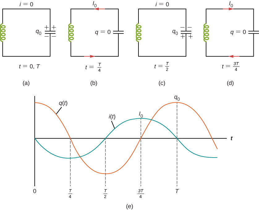
In (Figure)(b), the capacitor is completely discharged and all the free energy is stored in the magnetic field of the inductor. At this instant, the current is at its maximum value  and the energy in the inductor is

Since there is no resistance in the circuit, no energy is lost through Joule heating; thus, the maximum energy stored in the capacitor is equal to the maximum free energy stored at a later time in the inductor:

At an arbitrary time when the capacitor charge is q(t) and the electric current is i(t), the total energy U in the excursion is given by

Because there is no free energy dissipation,

Afterward reaching its maximum  the current i(t) continues to ship charge between the capacitor plates, thereby recharging the capacitor. Since the inductor resists a change in current, current continues to flow, even though the capacitor is discharged. This continued current causes the capacitor to charge with opposite polarity. The electric field of the capacitor increases while the magnetic field of the inductor diminishes, and the overall event is a transfer of energy from the inductor dorsum to the capacitor. From the law of energy conservation, the maximum charge that the capacitor re-acquires is
  However, as (Figure)(c) shows, the capacitor plates are charged reverse to what they were initially.
When fully charged, the capacitor once again transfers its free energy to the inductor until it is once more completely discharged, as shown in (Figure)(d). And then, in the last function of this cyclic process, free energy flows back to the capacitor, and the initial land of the circuit is restored.
We have followed the circuit through one consummate bike. Its electromagnetic oscillations are coordinating to the mechanical oscillations of a mass at the terminate of a spring. In this latter case, energy is transferred dorsum and forth between the mass, which has kinetic energy  , and the spring, which has potential energy
  . With the absenteeism of friction in the mass-jump system, the oscillations would continue indefinitely. Similarly, the oscillations of an LC circuit with no resistance would continue forever if undisturbed; however, this ideal null-resistance LC circuit is not practical, and any LC circuit will take at to the lowest degree a minor resistance, which volition radiate and lose energy over time.
The frequency of the oscillations in a resistance-free LC excursion may be constitute past illustration with the mass-leap system. For the circuit,  , the total electromagnetic energy U is

For the mass-jump system,  , the full mechanical energy Eastward is

The equivalence of the two systems is clear. To go from the mechanical to the electromagnetic system, we simply supercede thousand past 50, v by i, k by i/C, and x by q. At present x(t) is given by

where  Hence, the accuse on the capacitor in an LC circuit is given by

where the angular frequency of the oscillations in the circuit is

Finally, the electric current in the LC excursion is establish by taking the time derivative of q(t):

The time variations of q and I are shown in (Figure)(east) for  .
.
An LC Excursion In an LC circuit, the self-inductance is  H and the capacitance is
  F. At
F. At  all of the free energy is stored in the capacitor, which has charge
  C. (a) What is the angular frequency of the oscillations in the circuit? (b) What is the maximum electric current flowing through circuit? (c) How long does information technology take the capacitor to become completely discharged? (d) Find an equation that represents q(t).
Strategy The angular frequency of the LC circuit is given by (Figure). To observe the maximum current, the maximum energy in the capacitor is set equal to the maximum free energy in the inductor. The time for the capacitor to become discharged if it is initially charged is a quarter of the period of the cycle, so if we calculate the period of the oscillation, we can find out what a quarter of that is to find this time. Lastly, knowing the initial accuse and angular frequency, nosotros can set up a cosine equation to find q(t).
Solution
- From (Figure), the athwart frequency of the oscillations is

- The current is at its maximum when all the energy is stored in the inductor. From the law of energy conservation,

so

This effect tin also be plant by an analogy to uncomplicated harmonic motion, where current and charge are the velocity and position of an oscillator. - The capacitor becomes completely discharged in ane-quaternary of a cycle, or during a fourth dimension T/4, where T is the catamenia of the oscillations. Since

the fourth dimension taken for the capacitor to become fully discharged is
- The capacitor is completely charged at then
 Using (Effigy), we obtain

Thus, and
and

Significance The energy relationship ready in function (b) is non the simply way we can equate energies. At near times, some energy is stored in the capacitor and some energy is stored in the inductor. We can put both terms on each side of the equation. By examining the excursion but when there is no charge on the capacitor or no current in the inductor, nosotros simplify the energy equation.
Summary
- The energy transferred in an oscillatory manner between the capacitor and inductor in an LC circuit occurs at an angular frequency
 .
. - The accuse and current in the circuit are given past

Conceptual Questions
Do Kirchhoff'due south rules apply to circuits that incorporate inductors and capacitors?
yep
Tin a circuit element have both capacitance and inductance?
In an LC circuit, what determines the frequency and the amplitude of the energy oscillations in either the inductor or capacitor?
The amplitude of free energy oscillations depend on the initial energy of the system. The frequency in a LC excursion depends on the values of inductance and capacitance.
Bug
A 5000-pF capacitor is charged to 100 V and then quickly continued to an 80-mH inductor. Determine (a) the maximum free energy stored in the magnetic field of the inductor, (b) the height value of the current, and (c) the frequency of oscillation of the excursion.
The self-inductance and capacitance of an LC circuit are 0.20 mH and five.0 pF. What is the angular frequency at which the circuit oscillates?

What is the self-inductance of an LC circuit that oscillates at 60 Hz when the capacitance is  ?
?
In an aquiver LC excursion, the maximum accuse on the capacitor is  and the maximum current through the inductor is viii.0 mA. (a) What is the period of the oscillations? (b) How much time elapses between an instant when the capacitor is uncharged and the next instant when it is fully charged?
a.  ; b.
; b. 
The self-inductance and capacitance of an oscillating LC circuit are  respectively. (a) What is the frequency of the oscillations? (b) If the maximum potential divergence between the plates of the capacitor is fifty V, what is the maximum electric current in the circuit?
In an oscillating LC circuit, the maximum charge on the capacitor is  . Make up one's mind the accuse on the capacitor and the current through the inductor when energy is shared every bit between the electric and magnetic fields. Limited your answer in terms of , 50, and C.

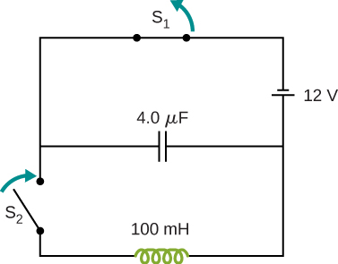
In the excursion shown below,  is opened and
  is closed simultaneously. Decide (a) the frequency of the resulting oscillations, (b) the maximum accuse on the capacitor, (c) the maximum current through the inductor, and (d) the electromagnetic energy of the oscillating excursion.
An LC circuit in an AM tuner (in a car stereo) uses a gyre with an inductance of 2.5 mH and a variable capacitor. If the natural frequency of the circuit is to be adjustable over the range 540 to 1600 kHz (the AM circulate ring), what range of capacitance is required?

Glossary
- LC circuit
- circuit composed of an ac source, inductor, and capacitor
Source: https://opentextbc.ca/universityphysicsv2openstax/chapter/oscillations-in-an-lc-circuit/
0 Response to "After What Fraction of Period T Will the Current Again Have Its Initial Value"
Publicar un comentario